FetchIt! - Grasp Cubes into Color-Matching Bins
Grasp Cubes into Bins 101
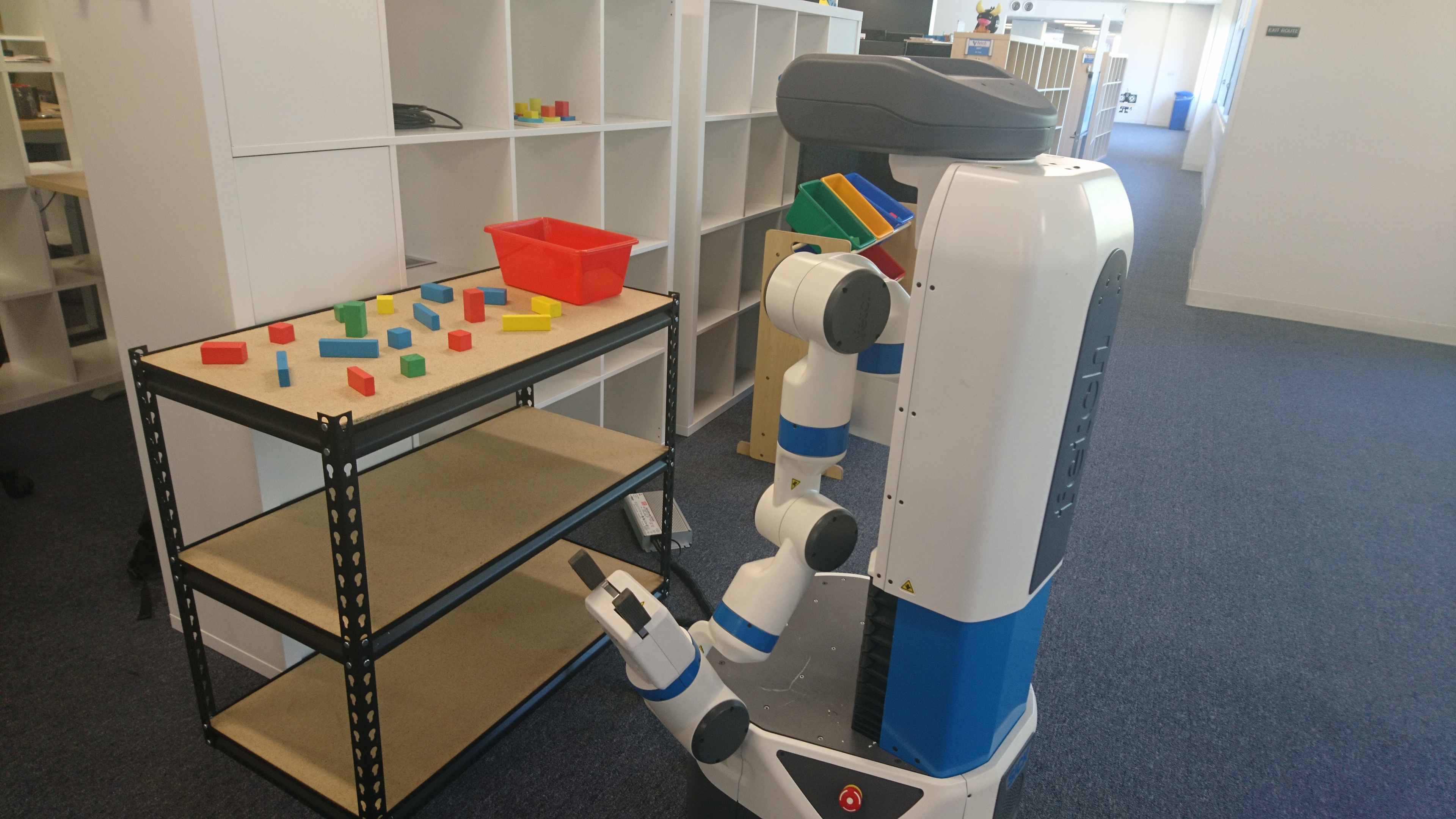
The Fetch is going to grasp the blocks into the bins that match the color. Here's a video that shows the Fetch grasping two cubes into the color-matching bin in simulation.
In the video, the Fetch will grasp the green cube into the green bin and the blue cube into the blue bin. The yellow cube will not be grasped because there is no matching bin in the scene.
System Structure
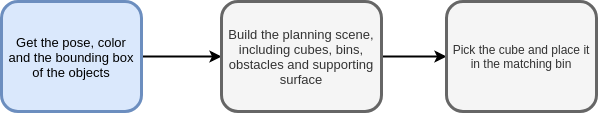
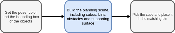
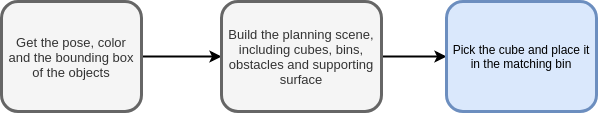
There are three main steps for this demo.
- Get the pose, color and the bounding box of the objects
- Build the planning scene, including cubes, bins, obstacles, and supporting surface
- Pick the cube and place it in the matching bin
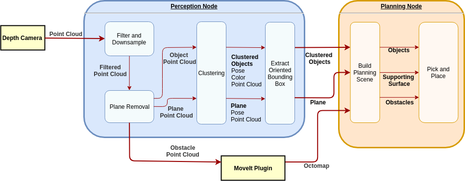
The whole system could be broken down into two nodes. One is the perception node and the other one is the planning node. The perception node will take in the point cloud from the Fetch depth camera and get the objects, plane, and obstacles information for the planning node. The planning node will process the object messages which contain pose, point cloud, color and bounding box of the objects and build a planning scene for picking the cube and placing it into the bin with the same color.
Terms:
- Objects: The cubes and bins placed on the table
- Obstacles: The things you don’t want to hit with the robot
- Object Point Cloud: The point cloud that only contains the objects
- Plane Point Cloud: The point cloud that only contains the plane
- Obstacle Point Cloud: The point cloud that contains the obstacles, without the plane
- Planning Scene: The environment built for the robot for it to know where are the objects and the obstacles. Basically, it’s a parallel world of reality.
- Supporting Surface: The supporting surface represents the table region in the planning scene. It needs higher precision than other obstacles like the wall behind the table so it’s added to the scene in the form of a collision object instead of octomap.
Get the pose, color and the bounding box of the objects
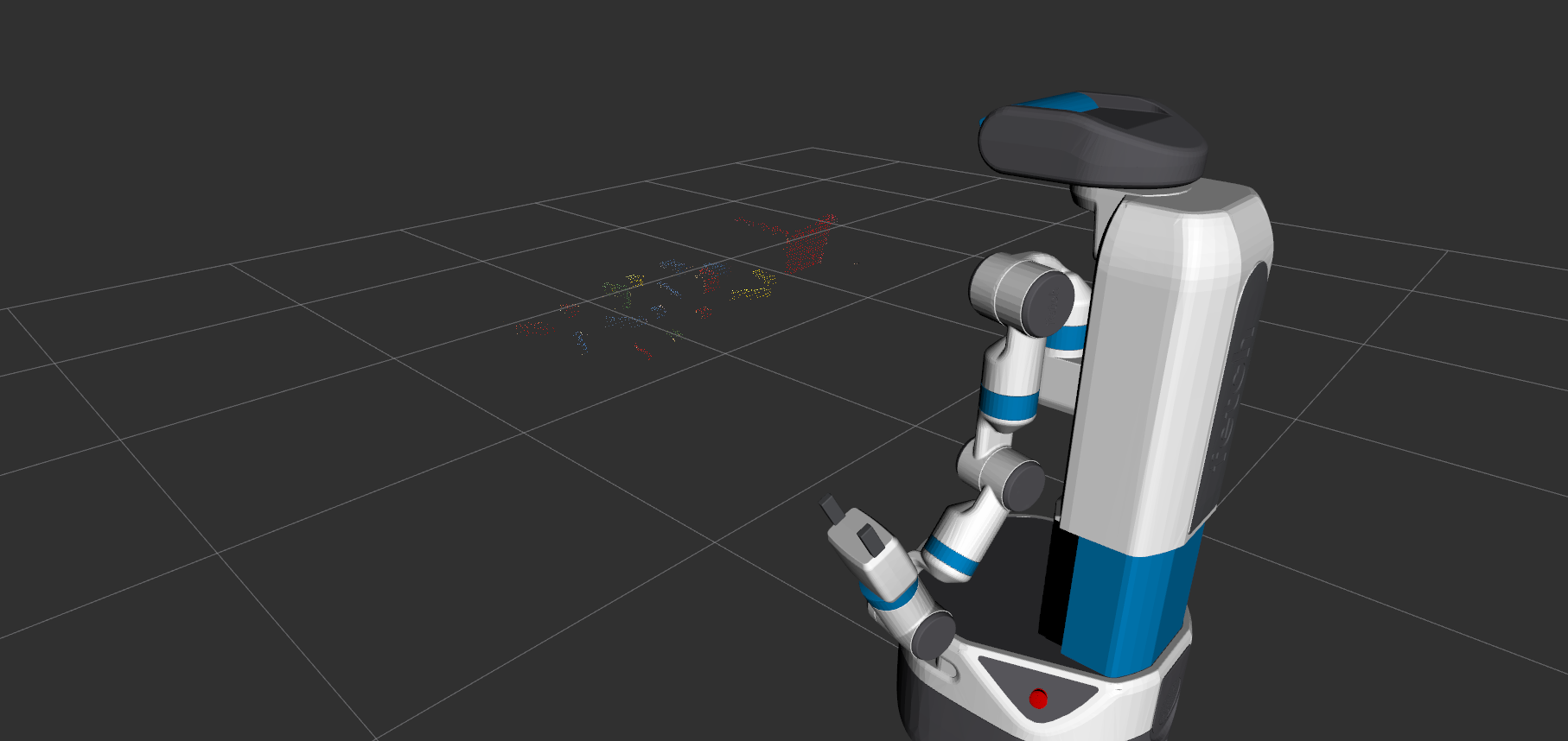
The planning node needs the pose, color and the bounding box of the cubes and the bins for picking and placing. In order to do so, the first step is to extract the object point cloud and cluster the objects. The strategy for extracting the object point cloud is to find the plane that has a similar height with the table surface and extract the point cloud that’s above the plane polygon. Here are the steps and illustration for the clustering.
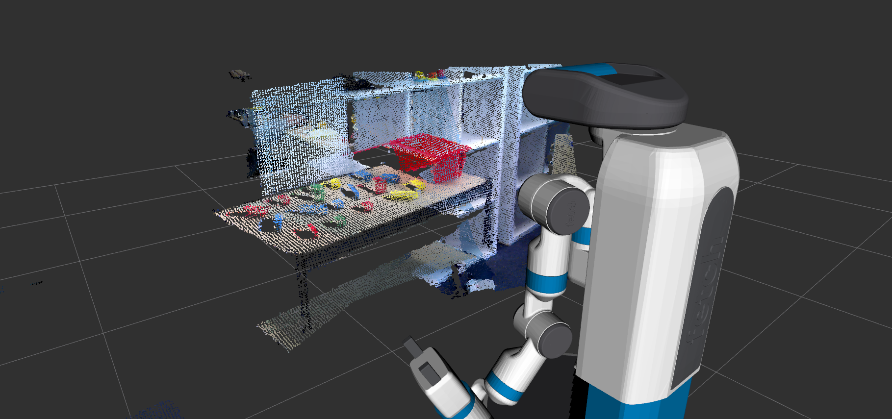
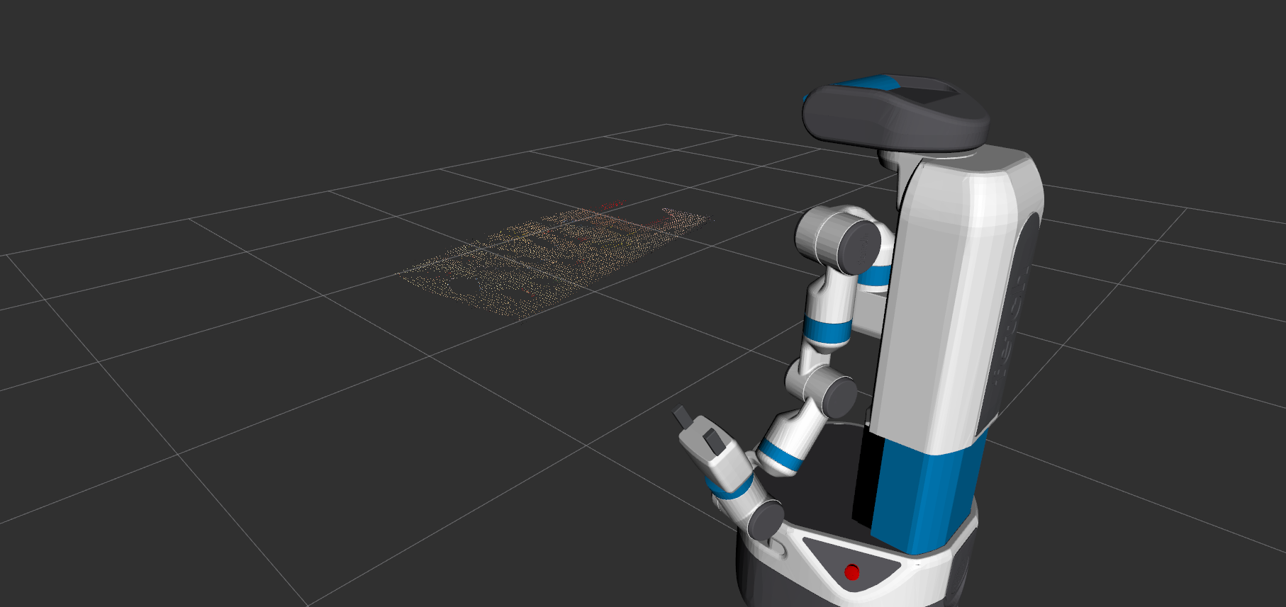
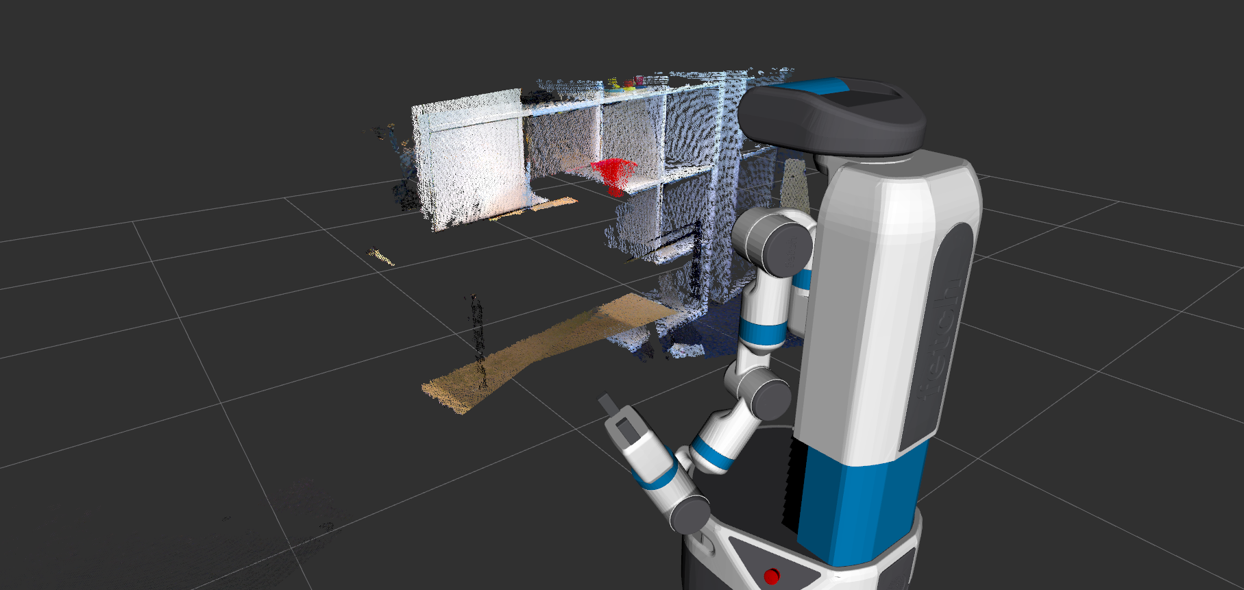
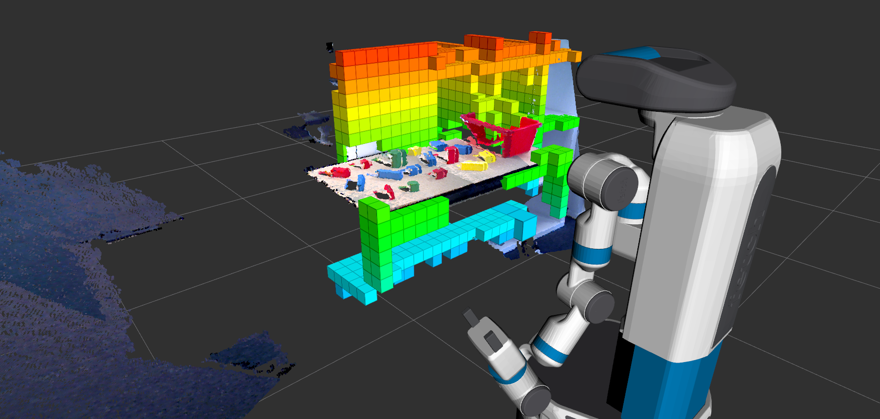
1. Scan the scene
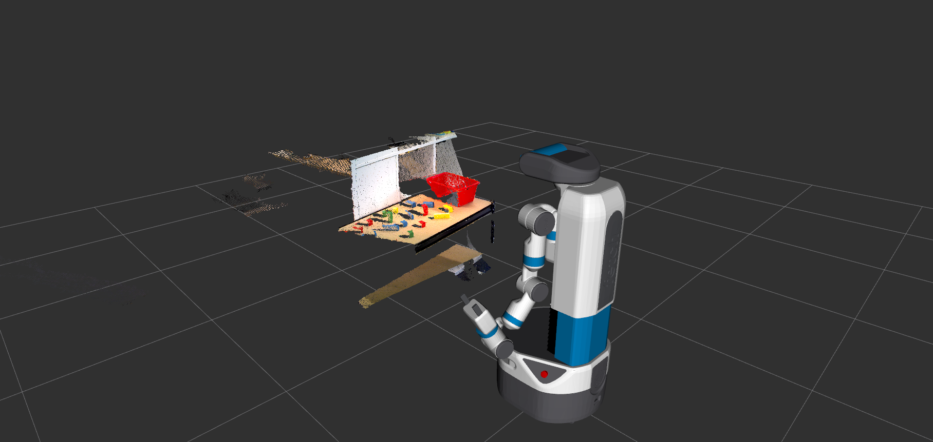
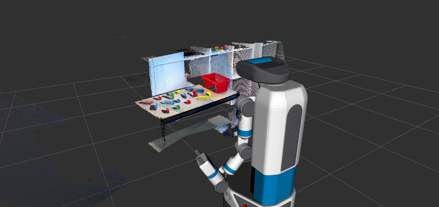
As the pictures show, the point cloud (on the left side) doesn’t cover all the objects and table region. In order to get the full view, the robot will scan the scene and process the point cloud combined from three views to get the objects, plane as well as the obstacles. The full scan point cloud is showing on the right side. The robot scan the scene from -30 degree to +30 degree relative to the origin to get a wider view of the scene.
void
PerceptionClustering::scanScene(pcl::PointCloud<pcl::PointXYZRGB>::Ptr& input_pcPtr, int degree_start, int degree_end)
{
 // get the height of the head pose and look at the origin at half of the head height
 pcl::PointCloud<pcl::PointXYZRGB>::Ptr sum_pcPtr(new pcl::PointCloud<pcl::PointXYZRGB>());
 geometry_msgs::PointStamped pt_head;
 geometry_msgs::TransformStamped transformStamped;
 geometry_msgs::TransformStamped initial_transformStamped;
 tf::Transform initial_transform;
 // keep the initial transformation to transform the point cloud into the same frame
 transform_frame(pt_head, 0.0, 0.0, 0.0, "base_link", "head_camera_rgb_optical_frame");
 ROS_INFO("the head position point: %f, %f, %f", pt_head.point.x, pt_head.point.y, pt_head.point.z);
 head_lookat(1.0, 0.0, pt_head.point.z / 2, "base_link");
 // the time out is for the head to slide into the exact pose
 ros::Duration(4.0).sleep();

 initial_transformStamped = lookup_transform( "head_camera_rgb_optical_frame", "base_link");
 tf::transformMsgToTF(initial_transformStamped.transform, initial_transform);
 int full_range = degree_end - degree_start;
 int sampling_time = full_range / 30 + 1;

 for (int i = 0; i < sampling_time; i++)
 {

   double cur_degree = degree_start + i*30;
   ROS_INFO("current degree %f, point %f, %f, %f ", cur_degree, 1.0, sin( cur_degree * PI / 180.0 ), pt_head.point.z);
   head_lookat(1.0, sin( cur_degree * PI / 180.0 ), pt_head.point.z / 2, "base_link");
   ros::Duration(5.0).sleep();

    //the transformation is to transform the point cloud into the same frame
   transformStamped = lookup_transform("base_link", "head_camera_rgb_optical_frame");
   tf::Transform transform;
   tf::transformMsgToTF(transformStamped.transform, transform);
   pcl::PointCloud<pcl::PointXYZRGB>::Ptr transformed_cloud (new pcl::PointCloud<pcl::PointXYZRGB> ());
   pcl_ros::transformPointCloud (*input_pcPtr_, *transformed_cloud, transform);
   ros::Duration(2.0).sleep();
   // combine the transformed point cloud together to get a wider view of the scene
   *sum_pcPtr += *transformed_cloud;

 }
 head_lookat(1.0, 0.0, pt_head.point.z / 2, "base_link");
 ros::Duration(3.0).sleep();
  pcl_ros::transformPointCloud (*sum_pcPtr, *input_pcPtr, initial_transform);

 ROS_INFO("finish scanning");
 ros::Duration(1.0).sleep();
}
The function scan will point the head from degree_start to degree_end in every 30 degrees. For the purpose of transforming the point cloud to a common frame, point the head to a center point first to get the transformation from base_link to the head at the center point. The transformation is called initial_transformStamped. After pointing the head to another point, get the transformStamped from base_link to the head and multiply it by the initial_transformStamped. Use the multiplied transformation to transform the point cloud to the same frame and add all the transformed point cloud together to get the point cloud with wider view.
2. Filtering
In order to speed up the processing time, the point cloud is downsampled into a lower resolution.
3. Plane Removal
Follow the tutorial from PCL plane detection to extract the planes from the original point cloud. Find the plane cluster that has a similar height and extracts it from the point cloud.
4. Extract the obstacle point cloud
Create a convex hull from the plane point cloud and extract the polygon prism from the plane point cloud. Set the lower bound to 2~4 cm below the plane and 6~10 cm above the plane. Everything outside this region is considered as obstacles. The PCL tutorial for constructing a convex hull is here.
5. Extract the object point cloud
Extract another polygon prism and set the lower bound to 1~ 2cm above the table and set the upper bound to 6~10 cm above the table. Point cloud within this region will be considered as objects. The parameters could be adjusted according to the size of the objects.
6. Cluster the object point cloud
Use the object point cloud to do the clustering. Set the parameters in the yaml file to adjust the effect of the clustering. After the clustering, we could get the position, color and the point cloud of the object.
7. Extract the oriented bounding box for the objects
The orientation is needed for the grasping purpose. The package ApproxMVBB is used to extract the oriented bounding box of each object cluster. The ROS wrapper of the ApproxMVBB, asr_apporx_mvbb is used in the node Code explained:
void
PerceptionClustering::extract_boundingbox(pcl::PointCloud<pcl::PointXYZRGB>::Ptr object_pcPtr,
                                        shape_msgs::SolidPrimitive& primitive,
                                        geometry_msgs::Pose& pose)
{
 ApproxMVBB::Matrix3Dyn mvbb_points(3, object_pcPtr->points.size());
 for (int i = 0; i < object_pcPtr->points.size(); i++)
 {
   mvbb_points.col(i) << object_pcPtr->points[i].x, object_pcPtr->points[i].y, object_pcPtr->points[i].z;
 }

 ApproxMVBB::OOBB oobb = ApproxMVBB::approximateMVBB(mvbb_points, 0.001, object_pcPtr->points.size(), 5, 0, 5);
 // store the position of the object
 float position_x =(oobb.m_maxPoint.x() + oobb.m_minPoint.x()) / 2;
 float position_y =(oobb.m_maxPoint.y() + oobb.m_minPoint.y()) / 2;
 float position_z =(oobb.m_maxPoint.z() + oobb.m_minPoint.z()) / 2;
 Eigen::Vector3f oobb_position(position_x, position_y, position_z);

 Eigen::Quaternionf rot(oobb.m_q_KI.w(), oobb.m_q_KI.x(), oobb.m_q_KI.y(), oobb.m_q_KI.z());
 oobb_position = rot.matrix()*oobb_position;
 pose.position.x = oobb_position.x();
 pose.position.y = oobb_position.y();
 pose.position.z = oobb_position.z();

 // get the orientation of the object
 pose.orientation.x = rot.x();
 pose.orientation.y = rot.y();
 pose.orientation.z = rot.z();
 pose.orientation.w = rot.w();

 // store the width, height, and depth of the object
 primitive.dimensions.push_back(oobb.m_maxPoint.x() - oobb.m_minPoint.x());
 primitive.dimensions.push_back(oobb.m_maxPoint.y() - oobb.m_minPoint.y());
 primitive.dimensions.push_back(oobb.m_maxPoint.z() - oobb.m_minPoint.z());

 ROS_INFO("in exract_boundingbox, max point: %d, %d, %d, %d", oobb.m_maxPoint[0], oobb.m_maxPoint[1], oobb.m_maxPoint[2]);
}
The function calculates the oriented bounding box for the clustered object. The function approximateMVBB takes an ApproxMVBB type object and the parameters to extract the oriented bounding box which contains the max point, min point, and the transformation matrix. The function was referenced from here.
Build the planning scene, including cubes, bins, obstacles, and supporting surface
The planning node should construct the planning scene for grasping. Now the perception node publishes the obstacle point cloud, plane point cloud and the object message including the color, point cloud, position, and the oriented bounding box. The planning node could use these to build the planning scene.
1. Turn the obstacle point cloud into Octomap for collision avoidance
The obstacle point cloud sometimes contains noises and the points that are out of the reach of the robot. The obstacle point cloud was processed with noise removal and range filtering (cut off the points that are out of the reach of the robot). After the filtering, publish the point cloud topic and modify the topic point_cloud_topic in the fetch_ros/fetch_moveit_config/config/sensors.yaml to the obstacle point cloud topic. Also, add a parameter called allow_active_sensing as true in the move_group.launch for the robot to publish the octomap in the planning scene.
2. Add the table and objectas a collision object
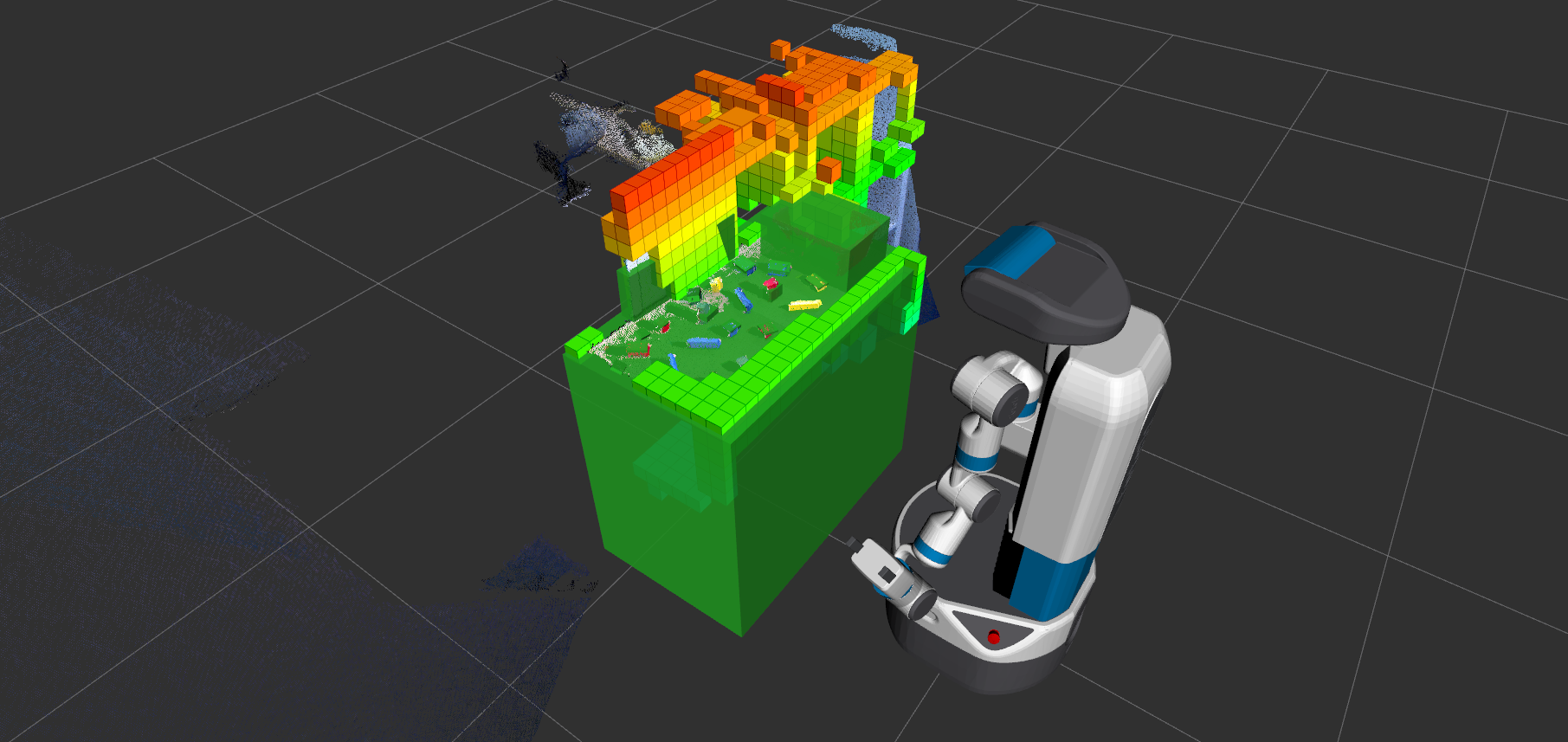
The green objects are considered as the collision objects in the planning scene. The robot will not collide to the collision objects while it plans the path. The table serves as a supporting surface that prevents the robot from crashing into the table. It needs higher precision than the octomap so it’s added as a collision object in the planning scene.
Pick the cube and place it in the matching bin
The robot picks the object that has a bin with matching color and places it into the bin. The robot picks the graspable object that is closest to it. The graspable object here means that there is at least one side that the robot could pick with the gripper and there is a matching bin in the scene.
The planning node will take in the pose of the cube and generate a path for the gripper to plan to it. After planning to the cube, it will remove the cube from the collision objects and turn the cube into an attached object (the purple object in the gif). An attached object means that the object is attached to a certain link and will allow collisions for specified links. For example, in this demo, the cube will be attached to the gripper link and is allowed to have collision with the grippers and the wrist. Whenever the robot arm moves, the attached object will also move relative to the attached link.
After the arm has moved to the placing area, the attached object will be placed and will become a collision object again after opening the gripper. All the collision object will be cleaned out for the next round of picking and placing.
Code explained for picking
def pick(self, obj, close_gripper_to=0.02, retry=1, tolerance=0.01, x_diff_pick=-0.01, z_diff_pick=0.1, x_diff_grasp=-0.01, z_diff_grasp=0.01):
       self.gripper_client.fully_open_gripper()
       angle_tmp = self.angle
       input_retry = retry
       success = False
       while angle_tmp <= self.angle_max and not success:
           radien = (angle_tmp / 2.0) * (pi / 180.0)
           rot_orientation = Quaternion(0.0, sin(radien), 0.0, cos(radien))
           obj_ori = obj.primitive_poses[0].orientation
           obj_quat = [obj_ori.x, obj_ori.y, obj_ori.z, obj_ori.w]
           roll, pitch, yaw = transformations.euler_from_quaternion(obj_quat)
           yaw_quat = transformations.quaternion_from_euler(0.0, 0.0, yaw)
           yaw_orientation = Quaternion(yaw_quat[0], yaw_quat[1], yaw_quat[2], yaw_quat[3])

           gripper_orientation = self.quaternion_multiply(yaw_orientation, rot_orientation)
           first_poseStamped = self.make_poseStamped("base_link", obj.primitive_poses[0], gripper_orientation)
           first_poseStamped.pose.position.x += x_diff_pick
           first_poseStamped.pose.position.z += z_diff_pick
           while retry > 0:
               move_pose_result = self.move_group.moveToPose(first_poseStamped, "gripper_link", tolerance=tolerance, PLAN_ONLY=True)
               rospy.sleep(1.0)
               if move_pose_result.error_code.val == MoveItErrorCodes.SUCCESS:
                   success = True
                   break
               else:
                   if move_pose_result.error_code.val == MoveItErrorCodes.NO_IK_SOLUTION:
                       rospy.loginfo("no valid IK found")
                   rospy.loginfo(move_pose_result.error_code.val)
               retry -= 1
           angle_tmp += self.angle_step
           retry = input_retry
       if retry == 0:
           return False

       success = False
       curr_retry = retry
       while angle_tmp  <= 90 and not success:
           radien = (angle_tmp  / 2) * (pi / 180)
           rot_orientation = Quaternion(0.0, sin(radien), 0.0, cos(radien))
           gripper_orientation = self.quaternion_multiply(yaw_orientation, rot_orientation)
           gripper_pose_stamped = self.make_poseStamped("base_link", obj.primitive_poses[0], gripper_orientation)
           gripper_pose_stamped.pose.position.z += z_diff_grasp
           gripper_pose_stamped.pose.position.x += x_diff_grasp
           while curr_retry > 0:
                move_pose_result = self.move_group.moveToPose(gripper_pose_stamped, "gripper_link", tolerance=tolerance)
               rospy.sleep(1.0)
               if move_pose_result.error_code.val == MoveItErrorCodes.SUCCESS:
                   success = True
                   break
               else:
                   if move_pose_result.error_code.val == MoveItErrorCodes.NO_IK_SOLUTION:
                       rospy.loginfo("no valid IK found")
                   rospy.loginfo(move_pose_result.error_code.val)
               curr_retry -= 1
           angle_tmp  += self.angle_step
           curr_retry = retry
           rospy.loginfo("closing the gripper")
           self.makeAttach(obj)
           self.gripper_client.close_gripper_to(close_gripper_to)
       if curr_retry == 0:
           return False
       rospy.loginfo("done picking")
       return True
Picking up a cube has two parts. The first part is moving the arm a little bit above the object. The gripper should be open and have the same orientation with the cube. The second part is to do the actual grasping which is moving the gripper down to the centroid of the object and then closes the gripper.
Let’s break down the code:
def pick(self, obj, close_gripper_to=0.02, retry=1, tolerance=0.01, x_diff_pick=-0.01, z_diff_pick=0.1, x_diff_grasp=-0.01, z_diff_grasp=0.01):
       self.gripper_client.fully_open_gripper()
       angle_tmp = self.angle
       input_retry = retry
       success = False
       while angle_tmp <= self.angle_max and not success:
           radien = (angle_tmp / 2.0) * (pi / 180.0)
           rot_orientation = Quaternion(0.0, sin(radien), 0.0, cos(radien))

	The gripper will rotate around the y axis and generate grasps from ```self.angle``` degree to ```self.angle_max``` degree. Each pose of the gripper could plan for multiple times if the input ```retry``` is greater than 1.


obj_ori = obj.primitive_poses[0].orientation
           obj_quat = [obj_ori.x, obj_ori.y, obj_ori.z, obj_ori.w]
           roll, pitch, yaw = transformations.euler_from_quaternion(obj_quat)
           yaw_quat = transformations.quaternion_from_euler(0.0, 0.0, yaw)
           yaw_orientation = Quaternion(yaw_quat[0], yaw_quat[1], yaw_quat[2], yaw_quat[3])

           gripper_orientation = self.quaternion_multiply(yaw_orientation, rot_orientation)
           first_poseStamped = self.make_poseStamped("base_link", obj.primitive_poses[0], gripper_orientation)
           first_poseStamped.pose.position.x += x_diff_pick
           first_poseStamped.pose.position.z += z_diff_pick
Extract the yaw orientation from the object and multiply the previous pitch orientation that the gripper is going to rotate. The new orientation will be the orientation of the gripper link. The position of the gripper link will be the position of the cube plus x_diff_pick in gripper link x axis direction and plus z_diff_pick in the gripper link z axis direction. The reason to do this is that if the we plan the gripper to the exact object position, the grippers might hit the object due to the observation errors.
    while retry > 0:
               move_pose_result = self.move_group.moveToPose(first_poseStamped, "gripper_link", tolerance=tolerance, PLAN_ONLY=True)
               rospy.sleep(1.0)
               if move_pose_result.error_code.val == MoveItErrorCodes.SUCCESS:
                   success = True
                   break
               else:
                   if move_pose_result.error_code.val == MoveItErrorCodes.NO_IK_SOLUTION:
                       rospy.loginfo("no valid IK found")
                   rospy.loginfo(move_pose_result.error_code.val)
               retry -= 1
           angle_tmp += self.angle_step
           retry = input_retry
       if retry == 0:
           return False
The planner uses the function moveToPose from MoveIt to plan the gripper to the pose and the planner could plan for retry times. If the planning result is unsuccessful, then the planner will continue planning until the retry times run out. If the planning is successful, then the function will return true.
The second part of the code is basically the same as the first part. Only that the second part is planning to the exact position of the cube with the same gripper orientation.